
RTL Design Engineer at Skyroot Aerospace

Hello, Dear Readers, Skyroot Aerospace has a vacancy for the RTL Design Engineer role. About Skyroot Aerospace: A cutting-edge startup founded by ex-ISRO scientists. Dedicated to affordable space access, we're rewriting aerospace technology rules. Our dynamic team fosters inventiveness, collaboration, and relentless excellence. Join us on a transformative journey to redefine space possibilities. Welcome to the forefront of space innovation with Skyroot Aerospace! Purpose of role: Understand architectural requirements and Design micro-architecture, implement design blocks using VHDL/Verilog for FPGA based Avionics packages for orbital launch vehicles and ground infrastructure. Job Requirements: 2+ Years of RTL and system design experience. Strong knowledge on Digital System Design (DSD). Strong knowledge of RTL/SoC design/integration with VHDL/Verilog. Strong knowledge in problem solving and debugging skills. Ability to understand architectural requirements and Design micro-archite...

CMOS Inverter-Layout Design And It functional Verification SPICE Simulation

 Hello Dear Readers,

Today, I will explain how to design a Layout in the MAGIC layout tool and how to perform SPICE simulation.

CMOS inverters (Complementary NMOSFET Inverters) are some of the most widely used and adaptable MOSFET inverters used in chip design. They operate with very little power loss and at relatively high speed. Furthermore, the CMOS inverter has good logic buffer characteristics, in that, its noise margins in both low and high states are large.

A CMOS inverter containing a PMOS and an NMOS transistor connected at the drain and gate terminals, a supply voltage VDD at the PMOS source terminal, and a ground connection at the NMOS source terminal Vin is connected to the gate terminals, and Vout is connected to the drain terminals As shown in Fig.1 is a circuit-level symbol but in the layout-wise internal structure of CMOS is consisted of common P-Type Substrate for building NMOS and N-Well implanted for building PMOS as shown in Fig.2.

                       Fig.1 CMOS Inverter

          Fig.2 CMOS Inverter Internal Structure

So Let's Start the Layout Once You Open the Magic Layout tool Screen is coming as shown in Fig.3. Go to the Window menu and click on "Grid on". So one grid is a square with one lambda by one lambda. So placing layers in magic we need to left-click hold it and right-click where we want to end the shape of the layer. So first I have to build N-well and p-type diffusion overlap as shown in Fig.4 all sizes are optimized by lambda-based design rules.

Fig.3 Magic Layout initial screen

Fig.4 N-well And p-type diffusion overlap

After that now we want to draw a polysilicon layer to build the gate terminal of PMOS. After that metal-1 and substrate contacts layer formed to build complete PMOS as shown in Fig.5. Similarly, we build NMOS and shorted Polysilicon of PMOS and NMOS together to the formed input terminal of the Inverter and shorted the drain layer to the formed output terminal as shown in Fig.6. After that we have to provide labels of VDD, gnd, in, and out as shown in the final layout.  

Fig.5 PMOS

Fig.6 CMOS Inverter final layout

So after the final layout save the layout go to the command line screen of the magic and type first "extract all" and then "ext2spice" as shown in Fig.7. Now go to path in which layout is saved so we found the .spice format file and .mag format file. So copy the .spice file and make a new directory on which paste it and then go to the PTM model and copy the entire web page and make the text file in the same directory on which the spice file was saved. Now open spice file and do some changes such as include model file, apply the supply voltage and input pulse signal for functional verification as shown in Fig.8.


Fig.7 Extract Layout

Fig.8 Updated SPICE file

Now open the terminal from this directory and open Ngspice with spice file as shown in Fig.9 and type command "run" first and then type "plot in out". The simulational waveform is shown in Fig.10.
Spoken Tutorial found Here.


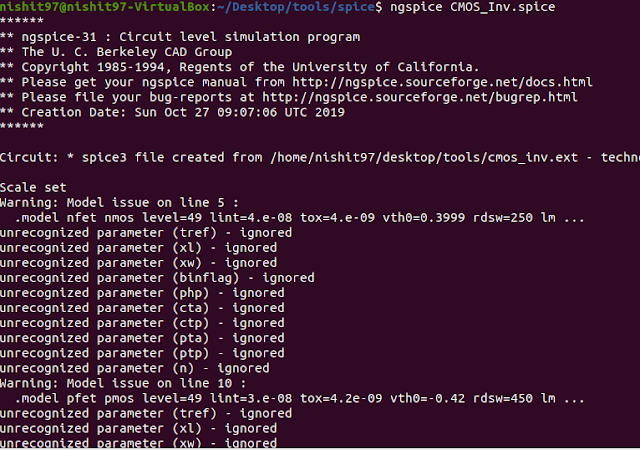
Fig.9 Ngspice simaltion
 
Fig.10 Simulation Waveform of CMOS Inverter


Connect with me 


Comments

  1. Wow first time all doubts regarding Magic plus Ngspice is solved.thanks for your effort

    ReplyDelete
  2. One of the blog in which I found this much easy explanation and project wise learning. Bro keep it up and never stop this work.

    ReplyDelete
  3. Fantastic learning based post.

    ReplyDelete
  4. You are a next level motivation person. Really in india I never find other blog such user friendly.

    ReplyDelete
  5. You are really slow learner, I really like your content accuracy specifically verilog code is always bugs free. So best wish and keep it up

    ReplyDelete
  6. Amazing! Accurate and very well explained.

    ReplyDelete
  7. This comment has been removed by a blog administrator.

    ReplyDelete
  8. Really helpful for beginners

    ReplyDelete
  9. So simple and solved all the query regarding extraction and spice simulation. Thanks dear for your effort 😢😢😢😢

    ReplyDelete
  10. One of the excellent post regarding layout verification through spice simulation. I read your post regularly and big fan of you πŸ‘πŸ‘and I am a professor at IITH.

    ReplyDelete
    Replies
    1. It's my motivation thanks sir for your feedback and appreciation. I will do my best forever.

      Delete
  11. One of superb article

    ReplyDelete
  12. Superb post I really like the way of the contents and simpler explanation.

    ReplyDelete

Post a Comment

Popular posts from this blog

Exploring the Role of LEF Files in VLSI Chip Design: A Beginner's Guide

Hello Dear Readers,   Today in this post, I will provide some deep insight into the LEF file role during the VLSI Chip Design process. In VLSI (Very Large Scale Integration) design, a LEF file is a file that contains information about the physical geometry of the standard cells used in a circuit. LEF stands for Library Exchange Format. A standard cell is a pre-designed logic cell that contains a specific function, such as a flip-flop or an AND gate. Standard cells are designed to be easily combinable and scalable to create more complex circuits. The physical geometry of each standard cell is defined in the LEF file. The LEF file contains information such as the width, height, and position of the pins and metal layers of each standard cell. It also contains information about the physical design rules that govern the placement of these cells on the chip. LEF files are important in VLSI design because they enable the interoperability of different design tools from different vend...

Internship - SoC /IP Design at NXP India

Hello Dear Readers, Currently, at NXP India  vacancy for  Internship - SoC /IP Design   role.   We are looking for a Master degree student with Electronics and Communication Engineering, or related field, with an emphasis on SoC design. This is a full-time internship with a duration of about 11-12 months. Job Responsibility: Working with our experienced design team to design state of the art SoC hardware specific segment applications like Automotive, IoT, voice/object recognition, security, smart connectivity and touch sensing . Assisting experienced engineers with End-to-end ownership of SoC Design, Verification and implementation (Physical Design). Design and verify digital and Mixed-signal IPs. Document designs and present results. Job Qualification: Master student in electronic/computer engineering Creative and positive mindset Good knowledge on CMOS technologies Great communication skills, interpersonal skills, teamwork skills and can-do attitude Desire for a ca...

IC Design Engineer at Broadcom

  Hello Dear Readers, Currently, at Broadcom vacancy for an IC Design Engineer role. Job Description: Candidate would be required to work on various phases of SOC physical design activities. The job will include but not limited to block level – floor-planning, partitioning, placement, clock tree synthesis, route, physical verification (LVS/DRC/ERC/Antenna etc). Should be able to meet congestion, timing and area metrics.  Candidate would be required to do equivalence checks, STA, Crosstalk delay analysis, noise analysis, power optimization. Should be able to implement timing and functional ECOs. Should have excellent problem-solving skill to help through congestion resolution and timing closure. Should have experience formal verification and timing analysis and ECO implementation. Experience with tools such as Innovus/Encounter, ICC, Caliber, LEC, Primetime etc is highly desirable. Candidate should be able to work independently and guide other team members. Should be ...