
Hello Dear Readers, Today in this post, I will provide some deep insight into the VLSI packaging evolution and innovations. Semiconductor packaging has evolved from a simple protective housing into a critical performance enabler. In the modern VLSI landscape, packaging is no longer an afterthought; it is a fundamental determinant of PPA (Power, Performance, and Area) metrics, often dictating the thermal limits and signal integrity of the final SoC. 1. Traditional Packaging Technologies: These methods are the workhorses of the industry, widely used for low-to-medium complexity devices where cost-efficiency is paramount. Wire Bonding (QFN, QFP, DIP): Wire bonding is the most mature interconnection technology. It uses thin gold, copper, or aluminum wires to connect the die's bond pads to the package's internal leadframe. Implementation: The die is attached face-up to a leadframe or substrate. A wire bonder uses thermocompression or ultrasonic energy to attach wires betwee...
Hello Dear Readers,
Today in this post, I will provide some deep insight into the floating point multiplier. It's design, algorithms, and implementation using Verilog HDL languages.
First, let us understand what is IEEE Standard 754 Floating Point Numbers.
The IEEE Standard for Floating-Point Arithmetic (IEEE 754) is a technical standard for floating-point computation which was established in 1985 by the Institute of Electrical and Electronics Engineers (IEEE). The standard addressed many problems found in the diverse floating point implementations that made them difficult to use reliably and reduced their portability. IEEE Standard 754 floating point is the most common representation today for real numbers on computers, including Intel-based PC’s, Macs, and most Unix platforms.
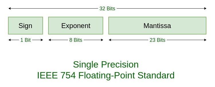
There are several ways to represent floating point number but IEEE 754 is the most efficient in most cases. IEEE 754 has 3 basic components:
- The Sign of Mantissa – This is as simple as the name. 0 represents a positive number while 1 represents a negative number.
- The Biased exponent – The exponent field needs to represent both positive and negative exponents. A bias is added to the actual exponent in order to get the stored exponent.
- The Normalised Mantissa – The mantissa is part of a number in scientific notation or a floating-point number, consisting of its significant digits. Here we have only 2 digits, i.e. O and 1. So a normalised mantissa is one with only one 1 to the left of the decimal.
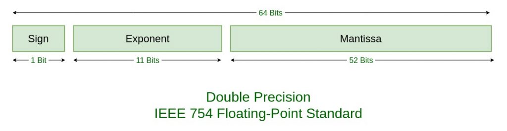
IEEE 754 numbers are divided into two based on the above three components: single precision and double precision.
| TYPES | SIGN | BIASED EXPONENT | NORMALISED MANTISA | BIAS |
|---|---|---|---|---|
| Single precision | 1(31st bit) | 8(30-23) | 23(22-0) | 127 |
| Double precision | 1(63rd bit) | 11(62-52) | 52(51-0) | 1023 |
Floating-point multipliers are crucial for handling arithmetic operations in various computational tasks. The floating-point multiplication algorithm can be complex, but here's a simplified breakdown:
Steps of Floating-Point Multiplication Algorithm
Extract the Components:
Decompose the two floating-point numbers into their sign, exponent, and mantissa (fraction) components.
For IEEE 754 single precision:
Sign: 1 bit
Exponent: 8 bits
Mantissa: 23 bits (with an implicit leading 1)
Compute the Result Sign:
The sign of the result is the XOR of the signs of the two operands.
If both signs are the same, the result is positive. If different, the result is negative.
Add the Exponents:
Add the exponents of the two numbers.
Adjust the sum by subtracting the bias (127 for single precision) to account for the excess-127 representation.
Multiply the Mantissas:
Multiply the mantissas (with the implicit leading 1).
This results in a product that is typically 48 bits for single precision (24-bit mantissa for each operand).
Normalize the Result:
Check the most significant bit of the mantissa product. If it is 1, the product is already normalized.
If not, normalize the product by shifting it left and adjusting the exponent accordingly.
Assemble the Result:
Combine the sign bit, the adjusted exponent, and the normalized mantissa to form the final floating-point result.
Example:
Let's work through an example to illustrate these steps.
Operands
A = 1.5 (in IEEE 754 single precision)
Binary: 0 01111111 10000000000000000000000
B = 2.0 (in IEEE 754 single precision)
Binary: 0 10000000 00000000000000000000000
Step-by-Step Calculation
Extract Components:
A: Sign = 0, Exponent = 127, Mantissa = 1.10000000000000000000000
B: Sign = 0, Exponent = 128, Mantissa = 1.00000000000000000000000
Compute Result Sign:
Result Sign = 0 XOR 0 = 0 (positive)
Add Exponents:
Exponent Sum = 127 + 128 = 255
Adjusted Exponent = 255 - 127 = 128
Multiply Mantissas:
Mantissa Product = 1.1 * 1.0 = 1.10000000000000000000000
Binary: 1.10000000000000000000000 (normalized)
Normalize the Result:
The product is already normalized (most significant bit is 1).
Result Mantissa = 10000000000000000000000
Result Exponent = 128
Assemble the Result:
Binary Result: 0 10000000 10000000000000000000000
Decimal Result: 3.0 (in IEEE 754 single precision)
Summary:
Floating-point multiplication involves:
Extracting the sign, exponent, and mantissa.
Calculating the result sign.
Adding the exponents and adjusting for the bias.
Multiplying the mantissa.
Normalizing the result.
Assembling the final result.
Let's dive into the Verilog code for a basic floating-point multiplier and explain each part in detail.
Verilog Code for Floating Point Multiplier:
module floating_point_multiplier (
input [31:0] a, // 32-bit Floating point number a
input [31:0] b, // 32-bit Floating point number b
output [31:0] result // 32-bit Floating point result
);
// Decompose the inputs into sign, exponent, and mantissa
wire sign_a = a[31];
wire sign_b = b[31];
wire [7:0] exponent_a = a[30:23];
wire [7:0] exponent_b = b[30:23];
wire [23:0] mantissa_a = {1'b1, a[22:0]};
wire [23:0] mantissa_b = {1'b1, b[22:0]};
// Calculate the result sign
wire result_sign = sign_a ^ sign_b;
// Add the exponents and adjust for the bias (127)
wire [8:0] exponent_sum = exponent_a + exponent_b - 8'd127;
// Multiply the mantissas
wire [47:0] mantissa_product = mantissa_a * mantissa_b;
// Normalize the result
wire [22:0] result_mantissa;
wire [7:0] result_exponent;
if (mantissa_product[47]) begin
// No need to shift mantissa
result_mantissa = mantissa_product[46:24];
result_exponent = exponent_sum + 1;
end else begin
// Normalize mantissa by shifting left
result_mantissa = mantissa_product[45:23];
result_exponent = exponent_sum;
end
// Combine the result
assign result = {result_sign, result_exponent, result_mantissa};
endmodule
This Verilog code demonstrates a basic floating-point multiplier compliant with the IEEE 754 single precision standard. The code can be further optimized and extended to handle exceptions like underflow, overflow, and special values (e.g., NaN, infinity).
Connect with me

Comments
Post a Comment